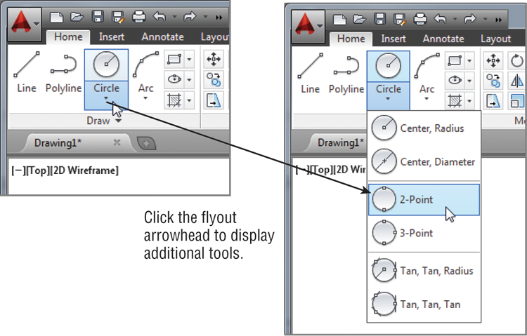
Specify the first, second & third point of the circle as shown in pic-5.ĭraw Circle By Using Tan Tan Radius ( TTR ).Specify the first point & second point of the circle as shown in pic-4.Specify the center point of the circle as shown in pic-3.Pic-2 Draw Circle By Using Center Diameter Specify the center point of the circle as shown in pic-2.There are 6 ways to make a circle in the drawing as shown in pic-1. By circle command, users can show the hole in the drawings. In Many drawings, users need to show holes. there is circle command in AutoCAD, therefore users can easily draw a circle. Users need to create the circles so many times in the drawings. (defun SortPipeData (pipeData / pipe tmp dataList) (setq dataList (cons (list (LM:roundto diameter 4) height) dataList)) (setq diameter (+ (- height) (sqrt (+ (expt height 2) (/ (* 2 area) pi))))) loop through to get lengths ('height') and radii/diameters (defun GetPipeData (ss / e cnt height area diameter dataList) Rounds 'n' to the nearest multiple of 'm' "\n - Total Length: " (rtos (caddr pipe) 4 3))) (prompt (strcat "\nPipe #" (itoa (setq cnt (1+ cnt))) (setq pipeData (GetPipeData ss)) <- returned format: ((dia length) (dia length). because as it stands currently, if you have a pipe with a 4.0001 diameter in your drawing and a pipe with 4.000 diameter, then these will be counted as 2 different pipe diameters. If your diameters will ALWAYS be to nearest 1" then this could be accounted for. ** I had to round your pipe diameters because they are inconsistent in your drawing (to nearest 4 decimal). I used Kent's idea to print the total pipe length to nearest 1/8", but this could be updated also (the precise value is still maintained in pipeData)
#Autocad lisp spiral from length and radius update
I rounded the diameters to 4 decimal places since your drawing was setup this way (but when they are printed to the command line you will only see 1 decimal place) (you should be able to tell where to update these) I think we're out by Voyager 1 at this point, Lol. If you find such a routine, on the question of which extent is the length compared with the diameter: if they're all circular in cross-section, two dimensions of such extents would have to both be diameters and therefore equal, so the one that doesn't match would be the length, whether longer than the diameter or not [and if all three are equal, it doesn't matter I am asking for the moon here I think with some Searching you might find approaches to finding the extents of such things, even at non-orthogonal angles, though I don't recall how it can be done.

And IF they were all of greater length than their diameter, one might hope to figure out from the bounding box dimensions which is which, but they're not. IF they all ran in 3D-orthogonal directions, one might hope to figure that out from their bounding boxes, but they don't. The entity data and properties for 3D Solids are entirely inscrutable for purposes of getting dimensional information such as what you're after. (setq dataList (cons (list radius height) dataList))Īgain, this process would be much easier if they were created as cylinders to begin with.ĮDIT: Please take note that the Radii and Lengths will be in the same units! (setq height (getpropertyvalue e "Height"))

loop through to get lengths ('height') and radius (defun GetPipeData (ss / e height area radius dataList) (prompt "\nHere is your pipe data as a list:\n") (setq pipeData (GetPipeData ss)) <- returned format: ((rad length) (rad length). (prompt "\nSelect Cylindrical Pipes Only: ") Then your items are returned as a list of radius/length pairs.įor the items I mentioned above, about not having height property, if they are selected then the function will error out.
#Autocad lisp spiral from length and radius code
Well until further refinements can be made, this code gets the 'height' and the 'area' of the solid, then calculates for the radius (perhaps there are rounding errors somewhere because I saw some 2 unit radius pipes being calculated as 1.99999 units).


 0 kommentar(er)
